Ethernet is the primary protocol that undergirds all modern camera control hardware. Each camera body is a little different—as is the Ethernet connector the manufacturer employs, and how that connector is wired.
The key to soldering your own camera control cables is using the proper connector and soldering the correct pin to the twisted pairs of RJ45 wires. If you want to make them like mine, I use black third party right-angle adjustable Lemo (Femo) connectors from eonvic. (Right-angle adjustable connectors have the prefix “FSG.” To learn more about Lemo connector nomenclature, please review Lemo catalog page 13.) In the case of Fischer, the connectors do not come in a right-angle variant, but eonvic still stocks them. I solder my connectors to pre-terminated Monoprice Micro SlimRun Cat6, which is a nice malleable cable stock for living on a camera build.
Connector Diagrams
If you want to make your own camera control cables—or QC ones you already own for proper wiring—you’ll need to reference the OEM diagrams. While most manufacturers provide pinout information in their official manuals, I have collated and cleaned up the information below for convenient perusal.
To test an Ethernet cable that only contains an RJ45 termination on one end, you can utilize female Lemo or Fischer connectors and connect that female receptacle or chassis connector to standard male RJ45 connector. Then you can just connect the two RJ45 ends to a standard RJ45 tester and ensure all eight pins are electrically connected.
For non-RJ45 connectors, please refer to the markings on your connector to determine the pin numbers to ensure you’re not visually reversing the pin numbers based on the angle at which you’re viewing the connector.
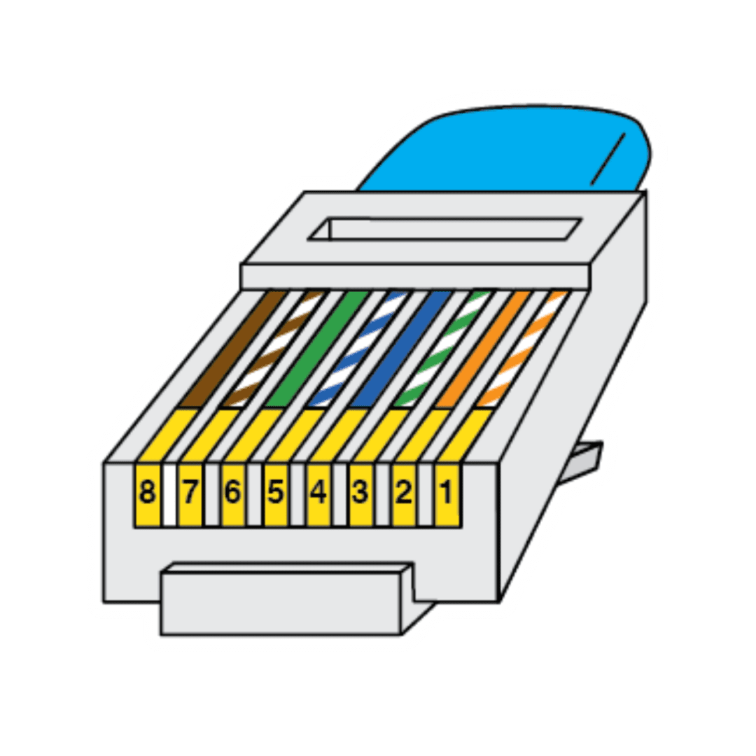
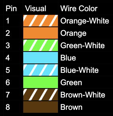
RJ45 (Used by Various OEM's)
RJ45 is what you may recognize as the “common” Ethernet connector. For camera control, you can use whatever type of RJ45 connector and cable stock combination that you’d like. If you’re making your own RJ45 to RJ45 cables, make sure you wire them consistently on both ends. T-568B is the preferred configuration, as displayed below (as opposed to T-568A). All Ethernet pinout color coding on this page refer to the T568B standard.
Some camera body manufacturers, like Vision Research and Panavision, utilize etherCON, which is a durable Neutrik-branded RJ45 connector that locks into place. Normal (non-etherCON) Ethernet cables are equally functional for transferring data via etherCON ports—they just aren’t as physically durable.
Arri
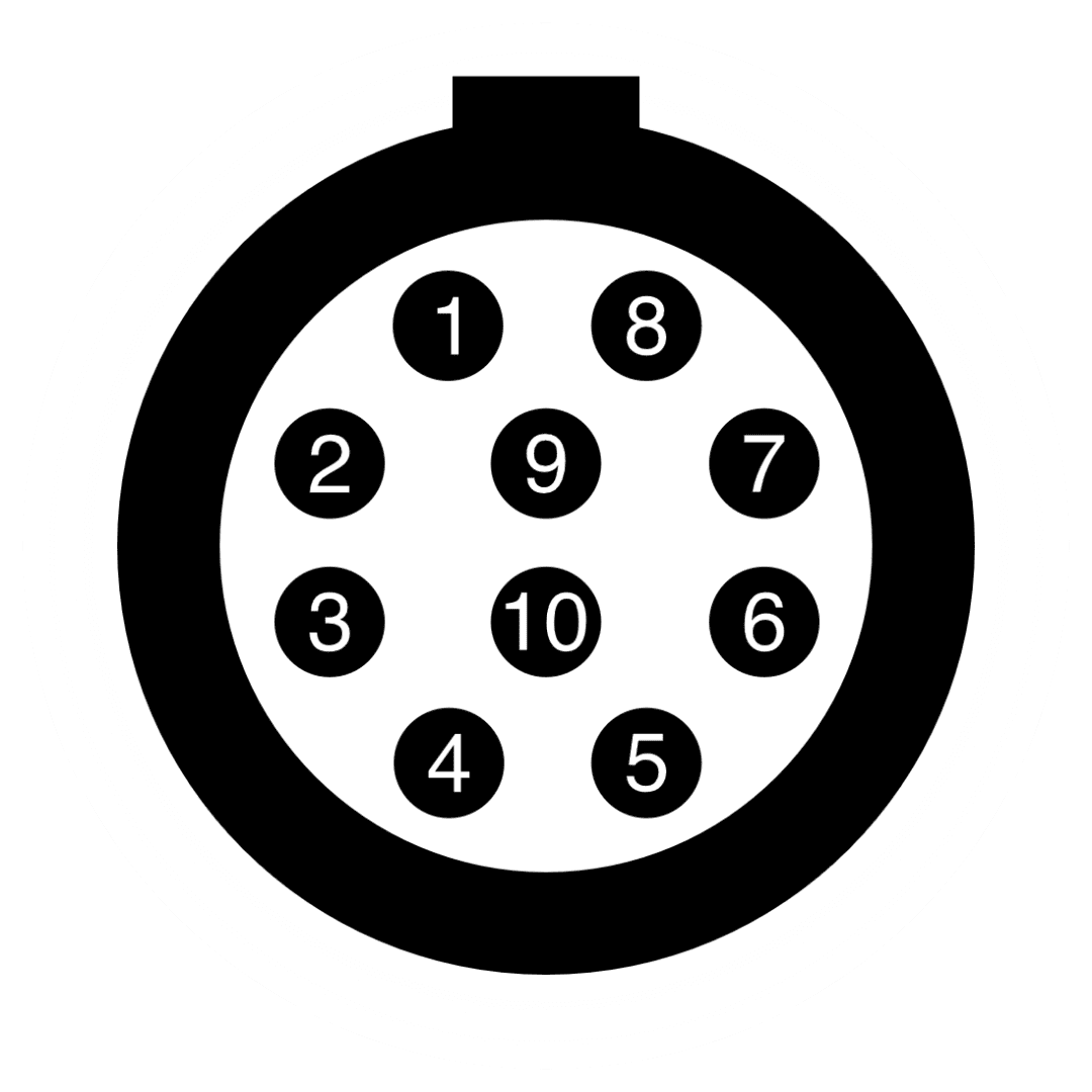
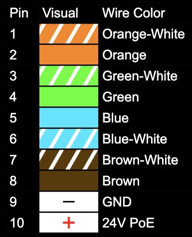
Many Arri camera bodies feature a Lemo 1B 10-Pin Ethernet connector. The angle of the Lemo keyway may vary. For a specific camera body keyway angle, please reference the Camera Gallery. Here are some example cable connectors:
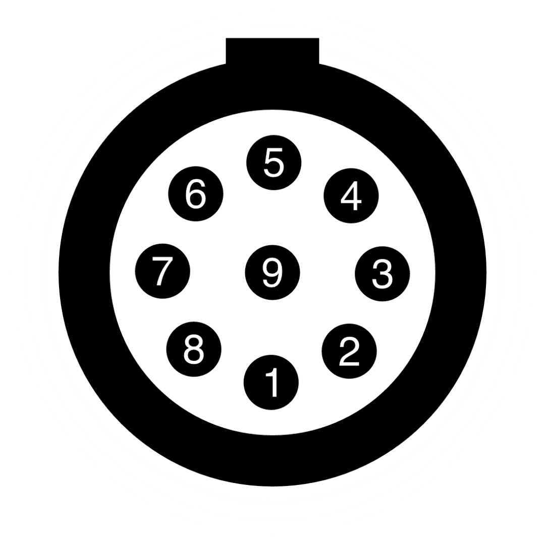
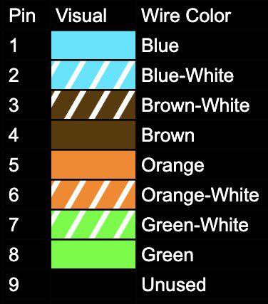
Many Red camera bodies feature a Lemo 0B 9-Pin Ethernet connector. The angle of the Lemo keyway may vary. For a specific camera body keyway angle, please reference the Camera Gallery. Here are some example cable connectors:
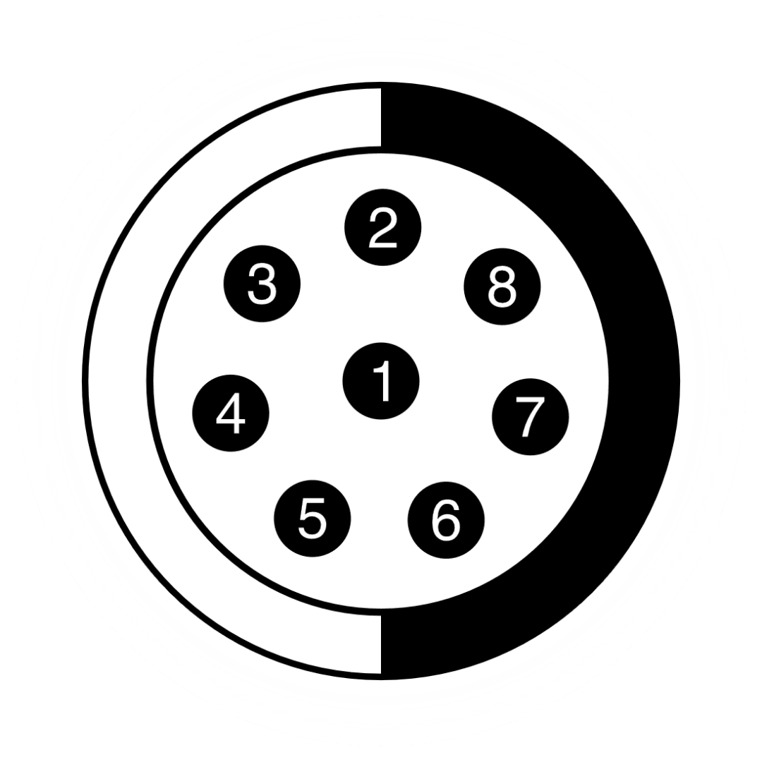
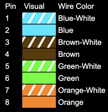
Many Vision Research camera bodies feature a Fischer 8-Pin Ethernet connector. The angle of the Lemo keyway is always as pictured below. To ascertain which connector your exact body uses, please reference the Camera Gallery. Here are some example cable connectors:
Semote features a Lemo 1B 10-Pin Ethernet connector. Two of your traditional eight Ethernet wires will have no connection. Here are some example cable connectors:
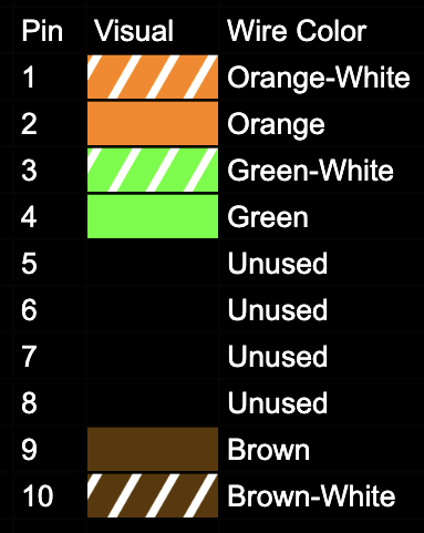
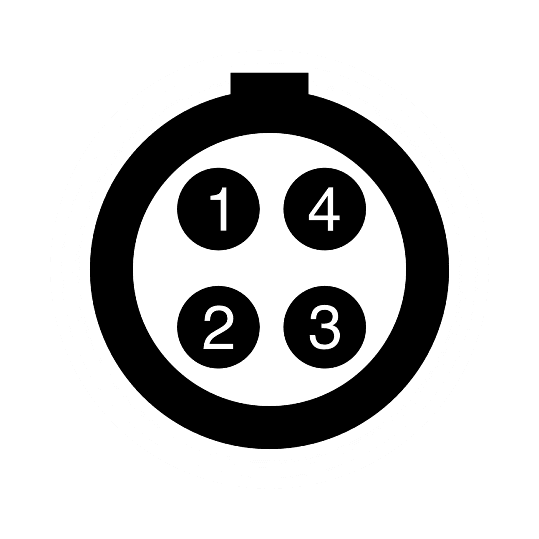
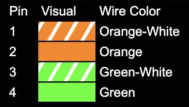
AtomLink features a 0B 4-Pin Lemo Ethernet connection. The following pinout corresponds specifically to T-568B, and four of your traditional eight Ethernet wires will have no connection. Here are some example cable connectors: